 English
 Russian

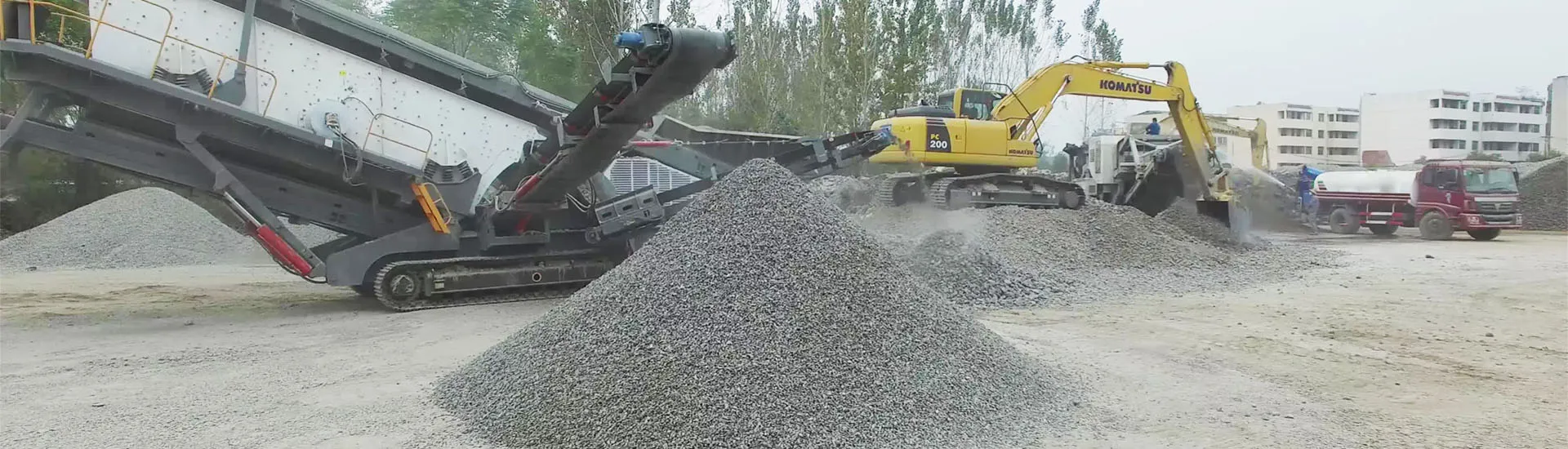
In high-specification manufactured sand production and aggregate shaping plants, the Vertical Shaft Impactor (VSI) crusher operating in rock-on-rock or rock-on-steel configuration is the primary machine for delivering cubic particle shape. However, because VSI rotors operate at circumferential tip speeds exceeding 60 to 85 m/s, wear component failure can destroy rotor balance within hours. Extending the operational life of tungsten carbide rotor tips and distributor plates requires rigorous metallurgical matching, feed flow velocity management, and strict dynamic balancing protocols.

Figure 1: High-capacity manufactured sand screening and shaping circuit powered by Sanming Machinery VSI Series crushers.
1. Tungsten Carbide Tip Metallurgy & Wear Mechanics
The rotor tips endure severe micro-chipping from high-velocity rock impact combined with intense sliding abrasion as rock slurry exits the discharge ports. Selecting the optimal tungsten carbide insert requires balancing hardness against fracture toughness:
Cobalt Binder Ratio (8%–12%): In hard, highly abrasive quartz, granite, or basalt feeds, an ultra-fine grain tungsten carbide with 9% to 11% cobalt matrix provides superior resistance to mechanical shock while maintaining a hardness rating of HRA 89.5–91.0.
Back-Up Tip Protection: The tungsten carbide insert must be supported by a ductile alloy steel holder. If the primary carbide tip fractures due to tramp metal or uncrushable oversize, the built-in cast alloy back-up tip shields the rotor port structure for up to 4–6 operating hours, preventing structural rotor body erosion.
Rotor Tip Geometry: Sanming Machinery High-Performance VSI Rotors utilize a split-tip multi-insert geometry. Rather than replacing a heavy, monolithic wear bar, operators replace only the high-wear lower tip segment, cutting wear component scrap weight by 45%.
2. Distributor Cone Geometry & Material Cushioning
The distributor cone (feed eye) positioned at the center of the spinning rotor receives the falling feed stream and accelerates it horizontally into the three or four internal rotor discharge chambers. When the distributor plate wears unevenly, feed streams divide disproportionately, causing catastrophic unbalance.
A properly formed autogenous rock lining inside the rotor pocket acts as the primary wear barrier: rock crushes against trapped rock, shielding the rotor walls. Maintaining this stone bed requires setting the distributor cone elevation exactly flush with the lower wear plate lip. If the cone sits too high, rocks ricochet against the upper wear plates; if too low, feed material surges under the distributor plate, destroying the hub mounting bolts.
| Wear Component | Recommended Material | Key Failure Mechanism | Maintenance Best Practice |
|---|---|---|---|
| Rotor Tips | WC-Co (Cobalt 9-11%) + CrMo support | Thermal cracking, carbide chipping | Replace in diametrically opposed pairs |
| Back-up Tips | High-chromium white cast iron (Cr26) | Abrasion after primary tip wear-through | Inspect every shift; replace before holder wear |
| Distributor Cone | Bi-metal cast alloy with carbide inserts | Center gouging, asymmetric wash-out | Rotate 90° weekly to balance circular wear |
| Upper/Lower Wear Plates | Abrasion resistant alloy steel (HARDOX 500) | Channeling grooves from fine rock wash | Check gap tolerances; seal with silicon bead |
3. Strict Dynamic Balancing Protocols to Prevent Bearing Destruction
Due to the rotational kinetic energy of a 1,000–1,200 mm diameter rotor spinning at 1,500 rpm, a weight discrepancy of merely 30 grams between opposite ports generates devastating centrifugal vibration forces. These vibrations transmit directly into the spherical roller bearings and drive shaft, leading to premature flaking and catastrophic cage failure.
Mandatory Balancing SOP:
Precision Weighed Replacement: New rotor tips, trail plates, and wear liners must be weighed on a digital gram scale prior to installation. Opposing components across the rotational axis must match within ±3 grams.
Opposed Pair Replacement: Never replace a single worn tip. If Port 1 is damaged, replace Port 1 and the diametrically opposed Port 3 simultaneously using weight-matched components.
Vibration Monitoring Limits: Sanming Machinery VSI Series comes integrated with dual-axis vibration sensors. Continuous vibration must remain below 4.5 mm/s RMS. A sudden spike above 7.0 mm/s automatically triggers motor interlock shutdown before structural fatigue occurs.
4. Technical FAQ: VSI Rotor Maintenance
Q1: Why do my carbide tips wear out within 20 operating hours?
A: The two primary culprits are oversize feed (rock particles exceeding 45–50 mm causing direct mechanical impact fracture) or operating with an empty material pocket due to insufficient fines in the feed loop.
Q2: How does moisture in the feed material affect rotor life?
A: Feed moisture between 3% and 7% causes rock packing inside the rotor eye, disrupting symmetrical discharge and inducing severe vibration. Feed must either be dried below 2.5% or washed in a wet circuit.
Q3: Can worn tungsten carbide tips be hard-faced with welding rods?
A: Absolutely not. Welding heat causes catastrophic thermal shock and micro-cracking in the tungsten carbide matrix and distorts the precision machined rotor body, creating severe balance hazards.
5. Precision Sand Making Engineering Support
Sanming Machinery engineers high-durability VSI rotors, tungsten carbide wear packages, and automated lubrication skids for aggregate producers worldwide. Contact our technical team for rotor speed calibration, fineness modulus control, and wear life guarantees.